The oil thread is a low depth path along the outside or inside of a profile where the main objective is to allow oil to pass though the part.
Others similar descriptions can be: relief groove, oil passage, oil channel among others depending on the documentation
Available after version 5.5.1.8 – this feature is experimental and should be used carefully.
The oil thread can be done on any profile, but since it is intended to allow oil to travel from one side of the profile to another, generally complete outside or inside face is chosen for this process.
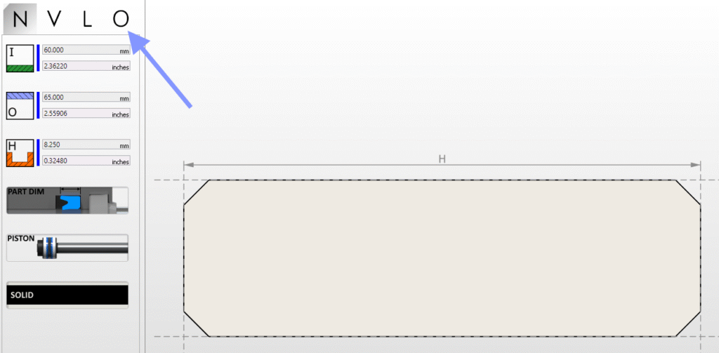
Step 1) Select operations
On the profile edit mode, go to operations:
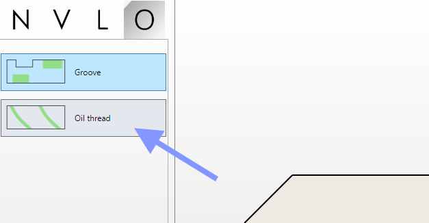
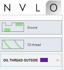
Step 2) Select Oil thread from the menu
Step 3) Select where the oil thread will be made
After selecting the oil thread, the mouse cursor will become a cross. This means that the system is on selection mode. Simply move the mouse on top of the drawing with the objective of selecting where the oil thread is going to be applied. A preview is shown highlighting the line where it will be made. See below example.
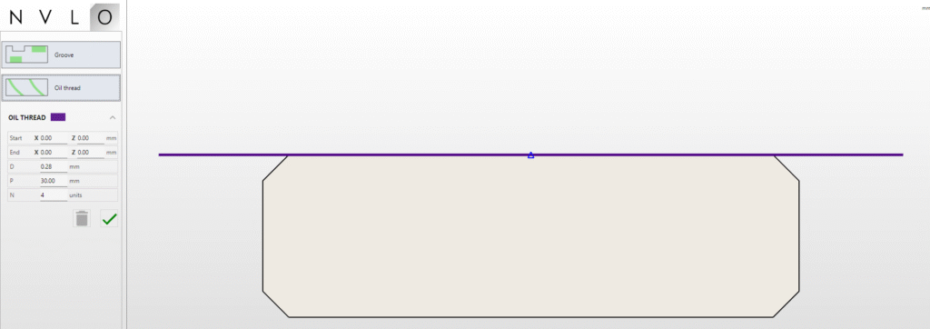
When the mouse was over the outside line, the purple line was added. This purple line is longer than the part itself because the oil tool movement requires a synchronized motion with the spindle. This is the normal situation and the default situation.
Until the user does not left click the mouse, it remains on “selection mode” and another line can be selected. During this period the textboxes on the left are unchanged.
Step 4) Confirm selection
By left clicking the mouse while a preview line is displayed, it will mean that the line is going to be selected. After it the mouse will enter the normal state (not selection mode) and the textboxes are filled with the relevant information. See below for example.
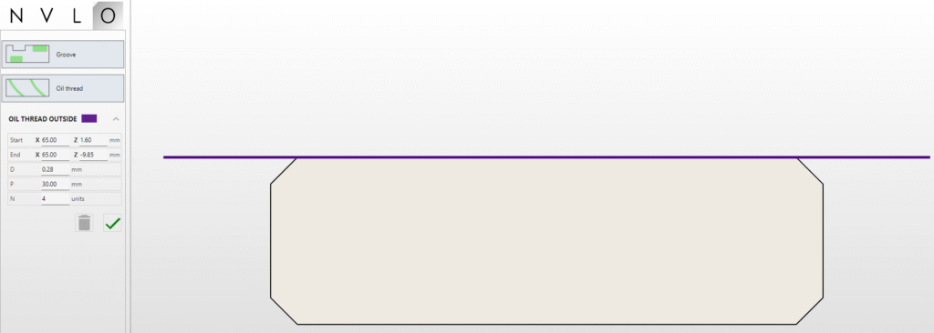
Textboxes can be changed if needed. Parameters are explained below:
| Name | Description |
| Start | X (diameter) and Z coordinates of the start of the thread movement made by the machine. It matches the preview line. |
| End | X (diameter) and Z coordinates of the end of the thread movement made by the machine. It matches the preview line. |
| D | Depth of the oil thread (radius). In this case 0.28 would be the oil thread depth made by the tool. |
| P | Pitch of the thread, in mm. In this case one full revolution of the spindle will correspond to 30mm movement in Z |
| N | Number of thread starts. In this case 4 oil threads will be made on the part |
When all is accordingly to the user request, press the accept button (green arrow) and the software will registered the oil thread.
More than one oil thread can be added per profile and the current oil thread can be edited by pressing the down arrow next to the oil thread information. The colour helps to identify what operation it is related.
Tooling selection
The tooling selection is automatic and it should be made by one of the already selecting tools that machined the outside (if the thread is outside). The same should happen for inside.
Warning: Due to many factors ensure that the oil thread is made after the outside or inside is fully machined to avoid collisions.
Example
Using the following set up on the machine settings for the thread, on Siemens 810D:
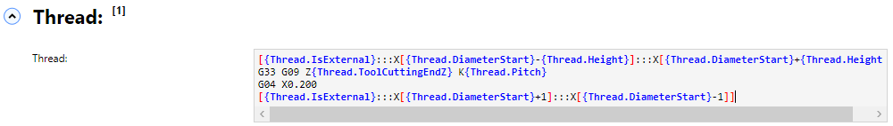
that corresponds to the text (useful for copy paste):
[{Thread.IsExternal}:::X[{Thread.DiameterStart}-{Thread.Height}]:::X[{Thread.DiameterStart}+{Thread.Height}]]
G33 G09 Z{Thread.ToolCuttingEndZ} K{Thread.Pitch}
G04 X0.200
[{Thread.IsExternal}:::X[{Thread.DiameterStart}+1]:::X[{Thread.DiameterStart}-1]]
will generate the following GCode:
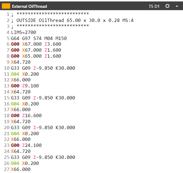
Note that 4 G33 are present that corresponds to 4 oil threads as requested.